
Burner Management Systems: How They Work and NFPA 86 Compliance
Every fuel-fired oven and furnace carries fire and explosion risk. The burner management system (BMS) is the layer of protection that keeps that risk in check, verifying conditions before a burner fires and cutting fuel the moment something falls out of limits.
This guide explains what a BMS is, how it sequences burner operation, the components it relies on, how it connects to your gas valve train, and how it supports NFPA 86 compliance for industrial ovens and furnaces. It also covers common trips, inspection, and when a retrofit makes sense.
| Key takeaway A Burner Management System (BMS) determines whether the burner is permitted to operate. It verifies required conditions, sequences ignition, supervises flame, and closes the safety shutoff valves when an unsafe condition is detected. |
What Is a Burner Management System?
A burner management system, or BMS, is a safety control system that sequences burner startup and shutdown, supervises flame and operating conditions, and cuts fuel when a condition falls outside safe limits. It decides whether a burner is allowed to fire and drives the equipment to a safe state when a fault occurs.
A BMS is not a combustion control system. The BMS handles safety, sequencing, and shutdown. The combustion control system handles firing rate and the fuel-to-air ratio that sets efficiency and process temperature. The two often work together, but their jobs stay separate.

What a Burner Management System Does
A BMS runs the safety sequence for fuel-fired equipment. Before ignition, it confirms a defined set of conditions is met. It then runs a purge, controls how pilot and main fuel are introduced, supervises the flame during firing, and forces a safe shutdown on a fault. The exact logic depends on the equipment, fuel, application, and adopted codes.
| Function | What it verifies or controls | Safety outcome |
| Permissive checks | Pressure, airflow, valve position, limit status | Blocks startup under unsafe conditions |
| Purge | Required airflow before ignition | Clears combustible mixtures from the chamber |
| Ignition sequencing | Pilot, igniter, and main flame order | Controls how fuel is introduced |
| Flame supervision | Presence of pilot or main flame | Cuts fuel if flame is lost |
| Fuel shutoff | Safety shutoff valves and actuators | Stops fuel during a trip |
| Alarm and diagnostics | Trip cause and system status | Supports safe troubleshooting |
Burner management systems run on industrial ovens, furnaces, kilns, dryers, and thermal oxidizers, which are the focus of this guide. Boilers and thermal-fluid heaters use the same class of system but can fall under different NFPA standards, so do not assume NFPA 86 covers every fuel-fired system in a plant.
How a Burner Management System Works
A BMS runs burner operation as a step-by-step progression, and each step depends on verified feedback from the equipment. The sequence below is representative, not a programming spec. Values such as trial-for-ignition times and purge air changes vary by equipment, fuel, and code edition.
It starts with pre-start permissives: emergency-stop status, combustion-air availability, gas pressure within limits, valve position, and process limits. Once those clear, the BMS runs and verifies the purge, moving air through the chamber to clear any combustible mixture before fuel enters.
Ignition follows. The BMS energizes the ignition source and opens the pilot valves in order. The flame detector must prove the pilot within the trial-for-ignition period, or the BMS closes the fuel valves and locks out. Main fuel is admitted only after the pilot is proven, and the BMS confirms the main flame within the permitted interval.
During normal firing, the combustion control system regulates demand while the BMS supervises safety in the background. A controlled shutdown reduces fuel and air in order. An emergency trip cuts fuel immediately. Postpurge follows where the sequence requires it, clearing residual fuel after the flame is out.
Key Components of a Burner Management System
A BMS is a coordinated set of logic, inputs, outputs, and final control elements, not a single panel. It helps to group the components by job: make decisions, sense conditions, ignite fuel, control fuel flow, and communicate status.
Safety Controller, Burner Control Unit, and HMI
The core may be a dedicated burner controller, a configurable flame-safeguard unit, or a safety-rated PLC such as a Siemens F-series, Rockwell GuardLogix, or HIMA platform. The choice depends on the application, burner count, and the independence and integrity the safety functions require. The HMI shows system state, active permissives, alarms, and trip history. It is an operator interface, not the device that performs the safety functions. SIL rating, redundancy, and independence from process controls vary by application and code.
Flame Detectors and Ignition Components
Ultraviolet, infrared, and flame-rod detectors each suit different conditions, and selection depends on burner type, fuel, flame characteristics, viewing position, cycle, and environment. Ignition components include igniters, ignition transformers, pilot burners, and their wiring and modules. Detector fault or degradation is one of the most common causes of nuisance trips. A marginal signal locks the system out, which is the correct response but points to maintenance rather than a design flaw.
Pressure Switches, Airflow Devices, and Limit Controls
These devices confirm conditions stay within limits. Common examples include high and low gas-pressure switches, combustion-air proving switches, temperature limits, process limits, and proof-of-position devices. They feed discrete or measured signals to the safety logic. They do not all do the same job, and each one has to be tested individually during a burner safety inspection rather than assumed good because the burner lights.
Safety Shutoff Valves, Actuators, and Valve Trains
Safety shutoff valves are the final control elements the BMS uses to stop fuel when the permissive to fire is removed. Actuators drive the valves, and proof-of-closure switches confirm they seated. Regulators, manual isolation valves, and pressure switches sit alongside them in an engineered gas valve train, covered next.
Industrial Gas Valve Trains and Fuel Trains
A gas valve train, also called a fuel train or valve safety train, is the assembly of valves, regulators, switches, and fittings that delivers fuel from the supply line to the burner. The BMS operates the safety shutoff valves inside it. The train is the physical fuel-handling and shutoff system, and its design affects both safety and compliance.
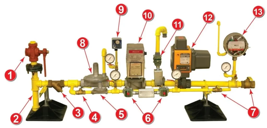
Gas Train Components
- Main Gas Shut-Off Valve
- Sediment Trap
- Strainer
- Pilot Gas Manual Valve
- Pilot Regulator
- Pilot Solenoid Valves
- Downstream Shut Off Valve
- Main Gas Regulator
- Low Gas Pressure Switch
- Safety Shut-Off Valve
- Double Block & Bleed Vent Valve
- Blocking Valve
- High Gas Pressure Switch
A typical train is built in segments. The inlet segment handles isolation, filtration, and pressure regulation. The safety segment holds the dual safety shutoff valves and proof-of-closure devices. The outlet segment manages firing rate and the manifold to the burner, and a pilot segment feeds the pilot. See how a valve train is laid out for a segment-by-segment view.
Standard components across all sizes include regulators, in-line strainers, dual-safety shutoff valves, manual isolation valves, pressure switches, and test fittings. Trains are pressure tested before delivery and built to meet or exceed NFPA, NEMA, NEC, CSA, UL, and FM standards.
Trains are also ventless or vented. Ventless components reference the room conditions where the burners sit, giving more stable year-round operation. Vented components need vent piping routed to approved locations, and those vent lines are a failure point that has to be inspected for leaks or blockages. That maintenance burden is one reason ventless designs are often preferred where the application allows.
Facilities can specify standard pre-engineered trains for common capacities or move to engineered-to-order valve train systems when fuel type, capacity, footprint, or ancillary controls call for a custom layout.
Burner Management System vs. Combustion Control System
Burner management and combustion control have related but different jobs. The BMS handles permissives, sequencing, flame supervision, and trip response. The combustion control system handles firing rate, the fuel-to-air ratio, and process demand such as temperature or pressure. They can share a platform, but the safety functions still need separation, integrity, and design review. When a fault occurs, the BMS governs the response and removes fuel. The combustion control system may reduce load, but it does not own the safety action.
| Topic | Burner management system | Combustion control system |
| Primary purpose | Burner safety | Process and combustion performance |
| Typical functions | Purge, ignition, flame supervision, trips | Firing rate, fuel-air control, temperature or pressure demand |
| Response to a fault | Removes fuel, enters a safe state | May reduce load, but the BMS governs safety |
| Typical inputs | Flame, valve position, limits, pressure and airflow permissives | Temperature, pressure, oxygen, flow, production demand |
| Operator value | Trip diagnostics and safe sequencing | Stability, efficiency, process control |
Two architectures are common. A standalone architecture uses dedicated BMS hardware that runs the safety sequence and talks to separate process controls. An integrated architecture combines interfaces or modules on one platform while keeping the safety functions properly separated. Standalone can simplify independent testing and lifecycle support. Integrated can cut panel count and streamline diagnostics. Neither wins outright, and the right call depends on hazard level, plant standards, retrofit complexity, cybersecurity, and maintainability.
How Burner Management Systems Support NFPA 86 Compliance
NFPA 86, the Standard for Ovens and Furnaces, addresses fire and explosion hazards for ovens and furnaces used in industrial material processing. A compliant BMS is required, but it is one part of the picture. Full compliance also depends on equipment classification, heating-system design, ventilation, commissioning, operation, inspection, testing, documentation, and the authority having jurisdiction.
| Standards note Confirm the edition adopted by your jurisdiction, the equipment classification, applicable amendments, and manufacturer and insurer requirements before specifying or modifying a BMS. NFPA 86 was updated with a Tentative Interim Amendment to the 2023 edition, so verify against the current NFPA source rather than a summary. |
The areas below are what an engineer or auditor evaluates in a BMS review. Treat each as something to verify against the applicable edition and the approved equipment design, not as a substitute for the standard.
| Standard | Scope |
| NFPA 85 | Boiler and combustion systems hazards, including many boiler applications |
| NFPA 86 | Ovens and furnaces used in industrial material processing |
| NFPA 87 | Fluid heaters and thermal-fluid systems |
Safety Interlocks and Permissives
A permissive is a safety check the BMS has to confirm before it advances the sequence. Common ones include a completed purge, low and high fuel-pressure limits, combustion-air proving, flame proving, high-temperature limit, valve position, and emergency-stop status. A permissive is a gate, not a convenience feature. The burner does not fire until the condition behind it is verified.
Redundancy and Component Reliability
NFPA 86 calls for redundancy in critical elements so a single failure does not defeat the safety function. That usually means dual safety shutoff valves in series, proof-of-closure devices, and SIL-rated components on higher-hazard applications. Redundancy is more often compromised in the field than in the original design, for example a bypassed proof-of-closure device or a non-code-listed valve used as a replacement. Both undermine the protection the standard requires.
Documented Control Logic and Sequences
A compliant system needs current documentation: an as-built sequence of operations, a cause-and-effect matrix, and accurate wiring drawings. When logic changes or devices are swapped, the documentation changes with them. Outdated or missing documentation is one of the most common audit findings. A facility can run fully compliant hardware and still fail because no one can prove how the system is supposed to behave.
Annual Testing, Inspection, and Recordkeeping
NFPA 86 requires periodic inspection and testing of combustion safety devices. A proper annual review includes interlock testing, safety shutoff valve tightness testing, flame safeguard testing, control logic verification, and a look at alarm and event logs. Records matter as much as the testing, and they should capture dated results, technician credentials, findings, corrective actions, and change history. An annual combustion safety audit evaluates the full system rather than the controller alone.
Common BMS Trips and Failure Modes
A trip means the BMS detected a condition that does not satisfy the safety logic. The fix is to find and correct the underlying condition, not to keep resetting. The matrix below is a diagnostic reference for operators and maintenance teams, not a bypass or repair procedure. Troubleshooting should follow approved procedures and qualified personnel.
| Condition | Possible indication | Safety response | Items to verify |
| Pilot flame not proven | Ignition failure or pilot trip | Close pilot fuel, lock out or recycle | Ignition source, pilot fuel, detector signal |
| Main flame not proven | Main-flame failure | Close main safety shutoff valves | Flame signal, valve operation, fuel pressure |
| Flame loss during firing | Flame-failure trip | Cut fuel immediately | Detector condition, burner stability, fuel-air |
| High or low gas pressure | Pressure permissive fault | Block startup or trip burner | Pressure switch, regulator, supply |
| Combustion airflow lost | Airflow permissive fault | Cut fuel | Fan, airflow switch, damper, pressure |
| Valve closure not proven | Proof-of-closure fault | Block light-off | Valve position, actuator, proof switch |
| Purge not completed | Purge permissive fault | Block ignition | Fan status, timing, damper, airflow proof |
| Safety limit opened | Limit or process trip | Shut down burner | Temperature, pressure, or process limit |
Repeated resets are a warning sign. Recurring trips point to an intermittent detector, a sticking valve, a drifting pressure condition, an airflow problem, a wiring fault, or combustion instability. Clearing the trip over and over hides the pattern needed to diagnose it and subjects equipment to repeated failed ignition attempts. Reviewing alarm history, sequence state, and field-device condition finds the cause faster, and persistent instability often calls for professional burner tuning rather than another reset.

BMS Inspection, Testing, and Operator Training
BMS reliability depends on more than the controller. A thorough burner safety inspection covers flame safeguards, safety shutoff valves, proof-of-closure devices, pressure switches, airflow proving, emergency shutdowns, permissives, alarms, ignition components, control panels, drawings, and sequence documentation. It should include visual condition, functional testing, setpoint verification, and a check for unauthorized bypasses. Where an inspection turns up worn or failing hardware, field service and repairs keep the system in a safe, compliant state.
Training closes the loop. Operators and maintenance staff should know the normal sequence states, what each permissive and alarm means, how to respond to a trip, escalation procedures, and the limits of authorized troubleshooting. This article is not a substitute for that training and should not be used to operate or modify safety controls. Rockford Combustion runs a hands-on NFPA 86 workshop that meets mandatory annual training requirements while building practical familiarity with fuel-train safety and interlock testing.
How Rockford Combustion Helps
Outside help pays off when a system is aging, documentation is incomplete, nuisance trips are climbing, or operations have drifted from the original design. Any of these is a signal to evaluate the burners, valve train, and safety devices before replacing the controller.
Rockford Combustion works across the full system, from custom combustion engineering and engineered valve trains to inspections, audits, tuning, and operator training. To scope a new BMS, plan a retrofit, or prepare for an inspection, start with a review of your existing combustion safety solutions and current system.