
Safety Mat Selection Guide: Pressure-Sensitive Mats, Light Curtains, and Perimeter Guarding Systems
Selecting the right area guarding device depends on hazard zone geometry, how often personnel need access, and the safety performance level your risk assessment requires. Pressure-sensitive safety mats, light curtains, and perimeter guarding systems each serve distinct functions under OSHA 29 CFR 1910.212, and they are most effective in combination. This guide covers how to size and configure safety mats, when light curtains are the right choice, how perimeter guarding integrates all three device types, and where safety bumpers fit.
What Is a Pressure-Sensitive Safety Mat and How Does It Work?
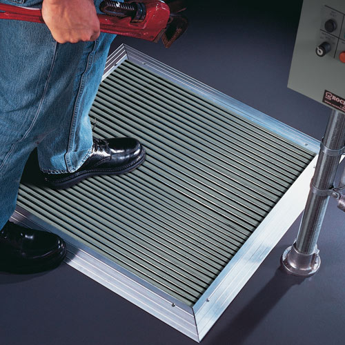
A pressure-sensitive safety mat is a presence-sensing device (PSD) under ANSI B11.19-2019. When properly integrated, when someone steps on the mat surface a stop signal travels to the machine control system which either prevents or stops hazardous motion.
The mat itself is passive. Through design, two separated conductive layers make contact under pressure, completing a circuit that signals the safety controller. The system is fail-safe and normally open (NO): any loss of power or break in the circuit defaults to the safe state. This is why safety mats are accepted as safeguarding devices under OSHA 29 CFR 1910.212(a)(1).
How Do Safety Mats Detect Presence and Initiate a Stop?
Under normal conditions, the two conductive layers are separated. Foot pressure compresses them, closes the circuit, and signals the controller. The controller opens the safety output relays and removes power from the machine drive. Sensitivity is set at the controller, not the mat. The mat actuates across its full active surface, with narrow, inactive edging around the perimeter.
What Category Rating Does a Safety Mat Controller Need?
The controller and critical safety-related componentry, not just the mat, determines the safety performance level of the system. Category 3 PLd controllers per ISO 13849-1 should be both self-checking and fault-tolerant which means that a single fault should not cause a loss of safety function.
For the highest-risk applications (robot cells, automated lines where a single failure could cause serious injury), Category 3 is the appropriate requirement. Verify the category and performance level against your risk assessment per ISO 13849-1 before specifying a controller. Appropriate safeguarding interface controls for safety mat integration are available from Rockford Systems. Specifying a Category 3 or Category 4 controller does not by itself make the entire safety system a Category 3 system. The system rating depends on every component in the safety function and on the risk assessment.
What Is a “Pressure Mat” and Is It the Same as an Industrial Safety Mat?
“Pressure mat” covers anti-fatigue mats, entrance mats, door alarm triggers, and general-purpose floor sensors with no machine safety function. In a safeguarding context, a pressure mat refers specifically to a pressure-sensitive safety mat: a pressure-sensitive device properly integrated into an appropriate safety controller. If you are specifying a floor-level safeguarding device for automated machinery, you need an industrial pressure-sensitive safety mat, not a general-purpose pressure mat.
How Do You Size and Configure Pressure-Sensitive Safety Mats for a Hazard Zone?
The mat or mat array must cover the entire hazard zone with no unprotected gaps. This flows from ANSI B11.19-2019, Section 8, and OSHA enforces through 29 CFR 1910.212(a)(1). Partial coverage does not satisfy these standards.
How Do You Measure and Define the Hazard Zone for a Safety Mat Installation?
Start with the hazard zone boundary, not the mat. The boundary is set by the minimum safety distance: the closest point at which a person standing on the mat edge can reach the point of operation before the machine completes its stop.
If your facility does not have stop-time data, Rockford Systems Stop-Time Measurement can provide that measurement before you finalize the mat layout.
When Does a Custom Safety Mat Configuration Make More Sense Than a Standard Size?
Standard mat sizes cover rectangular hazard zones with straightforward machine footprints. They can be modified with notches, cutouts, angles, or holes for irregular machine bases, drain covers, or column footings. Rockford Systems stocks standard pressure-sensitive safety mats from 12 inches by 12 inches up to a maximum single mat of 48 inches by 72 inches. The full standard size range is shown in the chart below. Custom mats beyond these sizes are available on request.
| Part No. | Width | Length |
| PSM-1212 | 12″ | 12″ |
| PSM-1224 | 12″ | 24″ |
| PSM-1236 | 12″ | 36″ |
| PSM-1248 | 12″ | 48″ |
| PSM-1260 | 12″ | 60″ |
| PSM-1272 | 12″ | 72″ |
| PSM-1636 | 16″ | 36″ |
| PSM-1824 | 18″ | 24″ |
| PSM-1836 | 18″ | 36″ |
| PSM-1848 | 18″ | 48″ |
| PSM-1860 | 18″ | 60″ |
| PSM-1872 | 18″ | 72″ |
| PSM-2420 | 24″ | 20″ |
| PSM-2424 | 24″ | 24″ |
| PSM-2430 | 24″ | 30″ |
| PSM-2436 | 24″ | 36″ |
| PSM-2442 | 24″ | 42″ |
| PSM-2448 | 24″ | 48″ |
| PSM-2456 | 24″ | 56″ |
| PSM-2460 | 24″ | 60″ |
| PSM-2472 | 24″ | 72″ |
| PSM-2828 | 27½” | 27½” |
| PSM-2833 | 27½” | 32½” |
| PSM-2843 | 27½” | 43″ |
| PSM-2856 | 27½” | 56″ |
| PSM-3030 | 30″ | 30″ |
| PSM-3036 | 30″ | 36″ |
| PSM-3042 | 30″ | 42″ |
| PSM-3048 | 30″ | 48″ |
| PSM-3060 | 30″ | 60″ |
| PSM-3072 | 30″ | 72″ |
| PSM-3432 | 33½” | 32″ |
| PSM-3444 | 33½” | 44″ |
| PSM-3456 | 33½” | 56″ |
| PSM-3636 | 36″ | 36″ |
| PSM-3642 | 36″ | 42″ |
| PSM-3648 | 36″ | 48″ |
| PSM-3660 | 36″ | 60″ |
| PSM-3672 | 36″ | 72″ |
| PSM-4132 | 40⅞” | 31 3/16″ |
| PSM-4144 | 40⅞” | 43 3/16″ |
| PSM-4156 | 40⅞” | 55 3/16″ |
| PSM-4848 | 48″ | 48″ |
| PSM-4860 | 48″ | 60″ |
| PSM-4872 | 48″ | 72″ (maximum size) |
For complex layouts around robot cells, press lines, or transfer machines with irregular hazard zones, custom configurations are typically more reliable than tiling multiple standard sizes. Gaps between improperly butted mat sections are one of the most common areas guarding deficiencies are found during safeguarding assessments. Custom configurations cover the full hazard zone geometry in a single validated layout.
ANSI B11.19 Requirements for Safety Mat Edge Treatment, Ramp Rails, and Anchoring
A mat edge that is not ramped or anchored creates two problems: a trip hazard for personnel approaching the zone, and a mat that shifts under foot traffic, potentially opening gaps in coverage. Neither is acceptable under ANSI B11.19-2019.
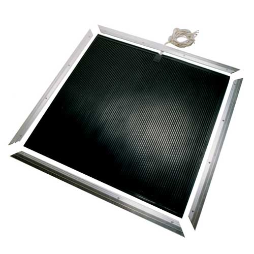
Tapered ramp rails and aluminum edge trim address the trip hazard and allow for proper anchoring of the mat. Ramp rail selection depends on mat thickness. Floor anchoring via expansion bolts or adhesive channels keeps the mat in position across shift-change foot traffic. Rockford Systems offers ramp edging, blunt edging, and mat connectors for all standard and custom mats. Custom mats beyond the standard sizes are available, so call for a quote.
How Do You Configure Safety Zones for Machine Perimeter Guarding in Automated Production?
Zone configuration starts with two distinct zone types. The exclusion zone is where the machine or robot operates without stopping for personnel. No entry is permitted during operation. The access zone is where personnel may enter for loading, unloading, or maintenance, and the machine stops when the zone is entered.
The safety mat system defines the inner boundary of the access zone. Perimeter guarding (barrier guards and light curtains at controlled openings) defines the outer boundary of the exclusion zone. These zones are not the same, and the devices that enforce them are not interchangeable.
What Is the Difference Between an Access Zone and an Exclusion Zone in a Safety Mat Layout?
The access zone is where presence detection matters: operators enter to work, and the machine must stop when they do. Safety mats are the primary presence-sensing device for the access zone floor. The exclusion zone is where no personnel should be present during operation. The boundary between the exclusion zone and adjacent work areas is enforced by physical barrier guards and interlocked entry points.
A common configuration error is using safety mats as the only control for a large robot cell perimeter without an interlocked entry gate. If the mat is the only device stopping the robot, any mat failure or bypass defeats the entire guarding system. ANSI B11.19-2019 requires complementary safeguarding when a single device cannot protect all entry paths.
How Many Safety Mats Can Be Connected in a Single Safety Circuit?
You can connect up to 10 safety mats in series to a single input channel on a Keyence GC or Banner XS-26 series safety controller, provided the total resistance of the series circuit does not exceed the maximum allowable input resistance (typically 100 to 200 ohms) and you maintain the required safety category. Exceeding this limit does not create an immediately visible unsafe condition, but it exceeds the controller’s monitoring range, which means the self-checking function no longer covers all mats.
For large hazard zones requiring more coverage than a single circuit supports, specify a second controller with its own circuit, and the two circuits can be co-integrated in a functionally safe manner.
When Should You Use Light Curtains Instead of (or Alongside) Safety Mats?
The distinction is spatial, not interchangeable. A safety mat detects presence in a floor area. A light curtain detects entry through a infrared beam plane emitted between the transmitter and receiver. These two detection geometries serve different design needs, and there can be instances where there is a need to use both.
A light curtain at the entry point of a mat-guarded zone detects access before a person reaches the mat. This gives the machine additional reaction time and protects the transition between the exclusion zone and the access zone. The mat handles floor-level presence detection inside the zone. The light curtain handles the entry plane.
Can a Light Curtain Designed for Perimeter Detection Substitute for Point-of-Operation Guarding Machinery?
No. A light curtain used for perimeter or area guarding uses wider channel spacing to detect whole-body presence. That spacing is not sufficient to detect finger or hand entry at a point-of-operation hazard. If your point-of-operation application requires a light curtain, specify a point-of-operation curtain with the resolution required by your risk assessment.
How Do Perimeter Guarding Systems Integrate Safety Mats, Light Curtains, and Barrier Guards?
A complete perimeter guarding system for an automated cell is not a single device. It is a set of complementary devices, each protecting a different entry path. ANSI B11.19-2019 Section 8.5 addresses complementary safeguarding: when a single device cannot protect all entry paths, additional devices are required.
There are three distinct elements: physical barrier guards defining the outer perimeter of the exclusion zone; light curtains or interlocked gates at controlled access points; and safety mats covering the access zone floor area inside the perimeter.
What Does a Perimeter Guarding Layout Look Like for a Robot Cell?
A typical robot cell: the outer perimeter is enclosed by barrier fencing or panel guards, with either a single or multiple controlled entry points. The entry has an interlocked gate that prevents robot operation when open. A light curtain is mounted at the gate opening to detect presence during entry before the person reaches the mat zone. Safety mats cover the floor inside the cell where operators stand during loading or maintenance.
When any device triggers (mat, light curtain, or gate interlock), the robot receives a stop command. The system is wired to a common safety relay or safety PLC so any single detection event stops the motion. Each device covers a different entry path, and together they leave no unprotected route into the hazard zone.
What Are the ANSI B11.19 Requirements for Interlocked Gates at Perimeter Guarding Entry Points?
Per ANSI B11.19-2019, interlocked barrier guards must prevent access during operation, and the means of interlocking must be control-reliable. A standard limit switch does not meet this requirement. A solenoid-controlled interlock or a magnetic safety interlock switch with a dual-channel monitored output does.
The interlock must be configured so the guard must be closed and locked before the machine can operate, and the machine must stop before the guard can be opened. Where stopping time exceeds the time it takes to open the gate, guard locking is required, not just guard monitoring. Specify whether the application requires locking or monitoring before selecting an interlock switch. Rockford Systems offers the Keyence interlock switch line shown below, including non-contact RFID switches and solenoid guard-locking models in both power-to-release and power-to-lock configurations.
| Model | RS Part No. | Description |
| GS-10PC | RKDS001 | Non-contact, simple type, PNP, 5-pin M12 (RFID) |
| GS-11P10 | RKDS002 | Non-contact, standard type, PNP, 8-core 10m cable |
| GS-11P5 | RKDS003 | Non-contact, standard type, PNP, 8-core 5m cable |
| GS-11PC | RKDS004 | Non-contact, standard type, PNP, 8-pin M12 |
| GS-13P5 | RKDS005 | Non-contact, high performance type, PNP, 12-core 5m cable |
| GS-13PC | RKDS006 | Non-contact, high performance type, PNP, 12-pin M12 |
| GS-51P10 | RKDS007 | Solenoid lock, power to release, standard type, PNP, 8-core 10m cable |
| GS-51P5 | RKDS008 | Solenoid lock, power to release, standard type, PNP, 8-core 5m cable |
| GS-51PC | RKDS009 | Solenoid lock, power to release, standard type, PNP, 8-pin M12 |
| GS-53PC | RKDS010 | Solenoid lock, power to release, high performance type, PNP, 12-pin M12 |
| GS-71P10 | RKDS011 | Solenoid lock, power to lock, standard type, PNP, 8-core 10m cable |
| GS-71P5 | RKDS012 | Solenoid lock, power to lock, standard type, PNP, 8-core 5m cable |
| GS-71PC | RKDS013 | Solenoid lock, power to lock, standard type, PNP, 8-pin M12 |
| GS-73PC | RKDS014 | Solenoid lock, power to lock, high performance type, PNP, 12-pin M12 |
Safety Bumper Applications: What Machines and Moving Equipment Need Pressure-Sensitive Edges?
Safety mats detect personnel standing in a defined floor zone. A safety bumper detects physical contact with a moving machine element: a powered sliding guard, a transfer car, or an AGV whose motion could crush or trap a person. The two devices address different hazard geometries.
A safety bumper is a pressure-sensitive edge mounted to the leading edge of a moving element. On contact, it initiates a stop and requires a manual reset before motion resumes. Each bumper includes an aluminum mounting channel, resistance to water, oil, hydraulic fluids, and coolants, and 4-lead wiring.
Safety Bumpers vs. Safety Mats: Which Application Fits Which?
Safety mats are right when the hazard is a floor zone: the machine is stationary and the person moves through the hazard area. Safety bumpers are right when the hazard is a moving element: the machine component moves and may contact a person or obstruction.
A powered sliding guard panel could require a safety bumper on its leading edge to detect a person caught in the closing path. The safety mat under the press detects the operator’s presence at the machine. These are different hazards requiring different devices, in the same installation.
Which OSHA and ANSI Standards Apply to Safety Mat and Perimeter Guarding Selection?
Rockford Systems is a voting member of the ANSI B11 Machine Safety Standards Committee. The B11 series is the primary framework applied in RS safeguarding assessments and engineering work.
What Does OSHA 29 CFR 1910.212 Require for Presence-Sensing Devices?
OSHA 29 CFR 1910.212(a)(1) requires that one or more methods of machine guarding be provided to protect employees from point-of-operation hazards, ingoing nip points, rotating parts, flying chips, and sparks. The standard does not prescribe specific devices. It requires that the guarding method prevent access to the hazard.
Presence-sensing devices, including safety mats and light curtains, are accepted under this standard when properly applied. “Properly applied” means the device is sized, positioned, and wired so it detects all access to the hazard zone and initiates a stop before contact with the point of operation. An undersized mat, a light curtain at insufficient clearance, or a mat array with unmonitored gaps does not meet this standard.
What Does ANSI B11.19-2019 Require for Safety Mat and Area Guarding System Design?
ANSI B11.19-2019 establishes performance criteria for the design, construction, installation, and use of safeguarding devices. For safety mats, Section 8.3 requires that the mat cover the full hazard zone, that the safety performance category of the control system match the risk assessment, and that minimum safety distance calculations be performed before installation.
Section 8.5 addresses complementary safeguarding: when a single device cannot protect all entry paths, additional devices are required. For light curtains classified as ESPDs under Section 8.3.2, the standard requires that the effective sensing surface be of adequate width and length so entry into the hazard zone is detected, and that reaching over, under, or around the sensing field is not possible without additional measures.
Frequently Asked Questions About Safety Mats and Area Guarding
OSHA 29 CFR 1910.212 does not mandate safety mats specifically. It requires that all machine hazard areas be guarded by one or more accepted methods. Safety mats are one accepted method when properly applied: sized to cover the full hazard zone, wired to a safety-rated controller, and installed in accordance with ANSI B11.19-2019.
A safety mat detects presence in a floor area by pressure. A light curtain detects entry through a vertical infrared beam field by interruption. Safety mats guard floor zones. Light curtains guard planes. Both are presence-sensing devices under ANSI B11.19-2019, and both are frequently used together.
You can connect up to 10 safety mats in series to a single input channel on a Keyence GC or Banner XS-26 series safety controller, as long as the total series resistance stays within the controller’s maximum allowable input resistance (typically 100 to 200 ohms) and the required safety category is maintained. Exceeding the rated maximum does not create an immediately visible unsafe condition, but it defeats the self-checking function required for Category 4 compliance. For larger areas, specify additional controllers rather than exceeding the rated series limit.
The controller monitors the mat circuit continuously and provides up to a Category safety function. These controllers pulse each mat at defined intervals to detect faults, tampering, and short circuits before they result in a failed stop. The mat is the passive detection surface. The controller is the safety-rated component that initiates the stop, monitors circuit integrity, and provides the compliant safety output.
Design Your Area Guarding System with Support from Rockford Systems
Selecting the right combination of pressure-sensitive safety mats, light curtains, and perimeter guarding components requires a risk assessment, a zone analysis, and a minimum safety distance calculation specific to each machine. There is no universal layout that satisfies OSHA 29 CFR 1910.212 and ANSI B11.19-2019 for every application.
Rockford Systems has conducted Machine Safeguarding assessments since 1971 and holds voting membership on the ANSI B11 Machine Safety Standards Committee. An assessment includes a site walkthrough, machine inventory, hazard identification, gap analysis, and a prioritized remediation plan with specific device recommendations.
To evaluate your area guarding design, contact Rockford Systems to schedule a Machine Safeguarding Assessment.
To view the full range of pressure-sensitive safety mats, safety bumpers, and area guarding products, visit the machine safeguarding product catalog.