SAFETY IN NUMBERS: Stop Time Measurements
Stop-Time Measurements Keep Safeguarding Equipment in Peak Performance
We’ve all heard the phrase “what a difference a day makes,” yet when it comes to industrial safeguarding, the concern isn’t days, hours or even minutes. It is the milliseconds it takes for a machine operation to stop. That fraction of a second can make the difference between a life-changing injury or a safe machine cycle, the difference between a valued employee going home or being taken to the emergency room.
How can we assure the right outcome?
How do we determine if a machine will stop in time?
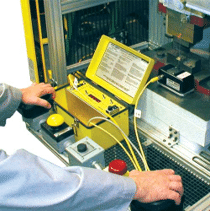 The answer is specialized equipment called “Stop-Time Measurement” devices (STM). An STM is used to determine the total response time from the triggering of a machine’s operating control or a safeguarding device… to the exact moment when a dangerous movement comes to a halt. Take, for example, the time it takes for a press brake cycle to stop when a finger or hand enters the point-of-operation zone, or the time between when a light curtain is activated and when the machine comes to a complete standstill.
Once the stop-time data is captured by an STM in either milliseconds or inches, it is applied to an established formula to calculate the minimum safety distance required to install safety devices. A record of the measurement can be printed out, or alternatively, the device can be plugged into a PC where the measurements can be recorded and documented.
Doing the Math
According to OSHA, the majority of machine-related accidents happen as a result of a reflex action or when the operator is not paying attention. For example, a machine operator may instinctively reach into the machine when there is an issue. Or they will be so focused on a task that they’ll cross the threshold into a hazardous area without being aware of it. In these events, it is critical that a machine’s safety devices stop operations before the hazard is reached. In addition, accidents may not be the fault of the operator at all. There are instances where integrators do not program the field of coverage — the area being monitored by the light curtain, for instance — at the proper safety distance and puts the operator unknowingly at danger.
So what is the correct distance? The basic calculation for ‘safety distance’ comprises approach speed, overall stop time and penetration depth factor.
The standard formula is below:
DS = K (T) + DPF
where:
DS = the safety distance
K = the maximum speed that an individual can approach the hazard
T = the total time to stop the hazardous motion
DPF = the depth penetration factor of the safeguarding device
There are other variations on this calculation; for example, where a light curtain is in operation, the calculation requires both the resolution and the response time of the light curtain to be factored. Most STM devices perform calculations internally so the operator doesn’t need to concern themselves with all the details of the math, only the results to act upon.
In the United States there are two formulas that are used to properly calculate the safety distance. The first, the OSHA formula, is the minimum requirement for the calculation of the safety distance. The second is the ANSI formula, which incorporates additional factors to be considered when calculating the safety distance. Rockford Systems recommends the use of the ANSI system since it is the more comprehensive of the two. The formula is included in ANSI standards B11.19-2010 and Robotic Industries Association (RIA) R15.06-1999 (R2009), as well as CSA Z142-10, Z432-04 and Z434-03.
Stop-Time Measurement Service
For all linear and rotating motion equipment, Rockford Systems offers STM service for newly installed safety devices as well as for the periodic validation of existing safety devices. Periodic safety distance validation with an STM is required for AOPD systems, light curtains, 2-hand control systems, emergency stop devices, pressure-sensitive protective strips or mats, interlocking guards, doors and gates, as well as other safety devices and controls equipment used during production. This is necessary since factors like maintenance, brake wear, and alterations can increase the machine’s stopping time. If a machine stops slower than it did when it was originally commissioned then components will need to be adjusted to continue providing the correct level of safety. Stop time measurement is able to detect changes at an early stage, so that appropriate action can then be taken. For these and other reasons it is important to perform at least an annual stop time analysis. Rockford Systems STM services are mainly employed on reciprocating (stroking or cycling) machines, such as mechanical or hydraulic presses and press brakes, but can also be used on machines that rotate, such as lathes, mills, and drills.
Location of a safety component, whether hard guarding or electronic, is based upon the machine’s stopping time. Simply stated, a safety component should be placed far enough away from the risk area that it is not possible to reach the hazard before the machine has stopped. Safety devices are then installed using the minimum safe distance. Reference our OSHA Safety Distance Guide Slide Chart.
Regularly checking shop machinery with Stop-Time Measurements and maintaining a log of the results empowers a company to be proactive in establishing a safety maintenance program. It ensures that safeguarding equipment on machinery works as designed to achieve greater worker safety, productivity and profits.